This manual mainly introduces the installation, technical specifications and application examples of ES10 bender control system products. It is used in our
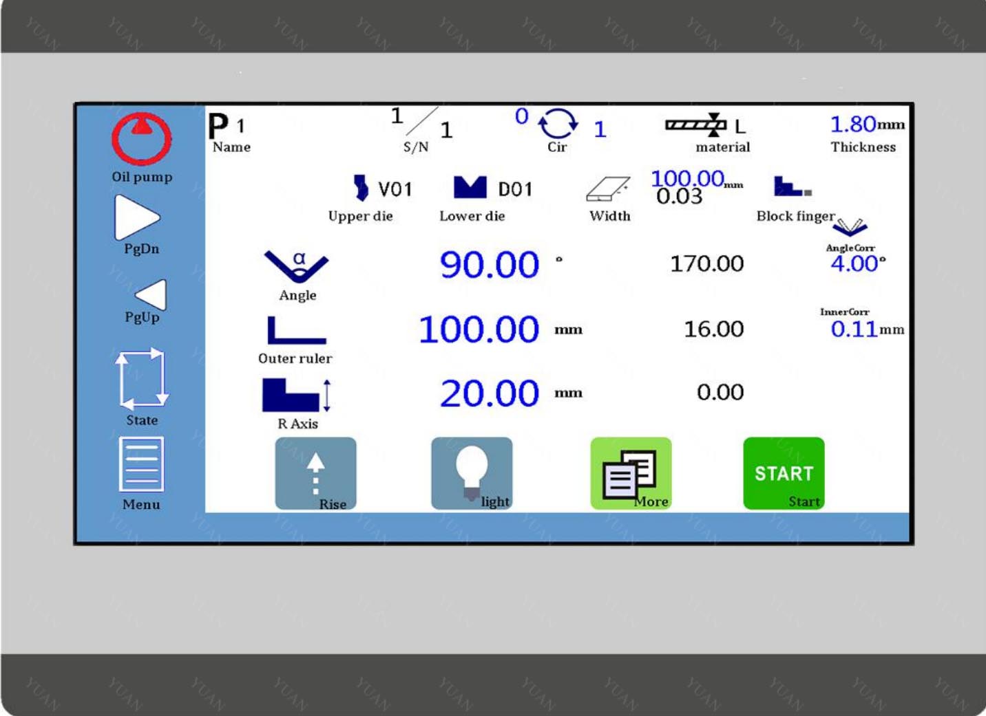
The contents of each chapter are summarized as follows.;
Chapter 1 (Operating Panel) Introduces the Use of Operating Panel of Bending
Machine Control System;
Chapter 2 (Application Examples) Illustrates how to operate the control system with
examples;
Appendix Q provides the interface specifications and common problems handling of various devices in the system for users to browse quickly.
Applicable object
This manual provides information on the installation and commissioning of ES10 bender control system products, designed for engineers, maintenance personnel and electricians with general automation knowledge.
1 Overview
1.1 Programm/Running
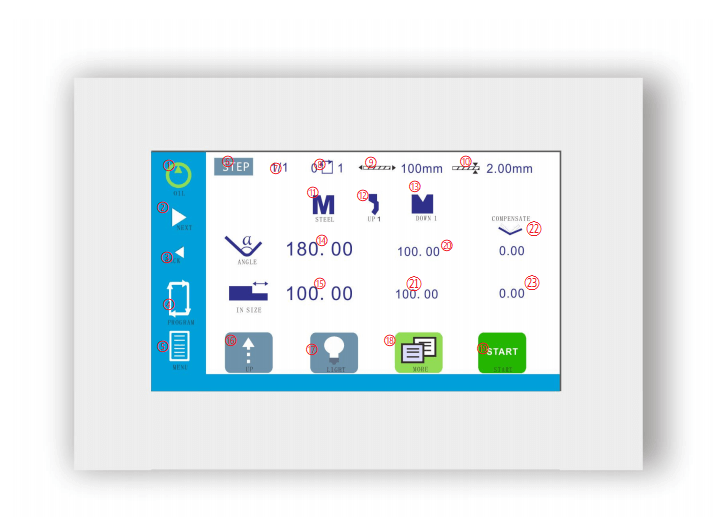
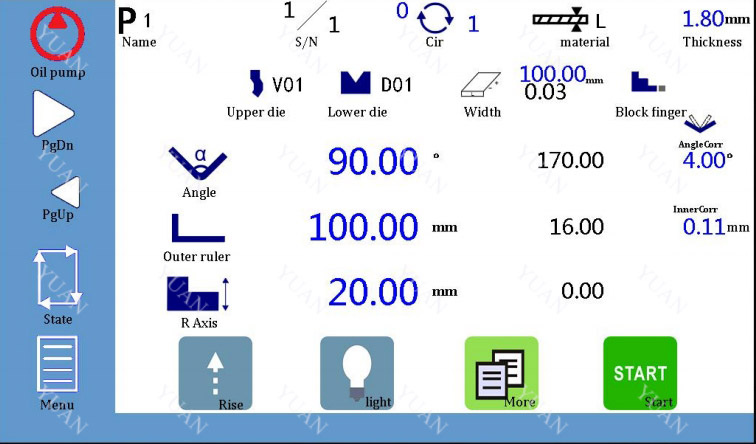
① Oil pump start ② Next step ③ Previous Step ④ Machine State ⑤ Menu ⑥ Program selection ⑦ Current step/total step ⑧ Current cycle count/total cycles ⑨ Length of plate ⑩ Plate thickness ⑪ Material Select ⑫ Upper Punch parameters | ⑬ Lower die parameters ⑭ Target Angle ⑮ Target location ⑯ Rise ⑰ Light ⑱ More Data Pages ⑲ Run/Stop ⑳ Current depth of Y axis ㉑ Current position ㉒ Angle compensation ㉓ Compensation |
More data setting:
Click on the icon  on the main page of programming ,You can access more data setting page.
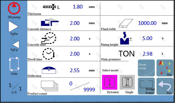
Table 1-1 Introduction of Parameters
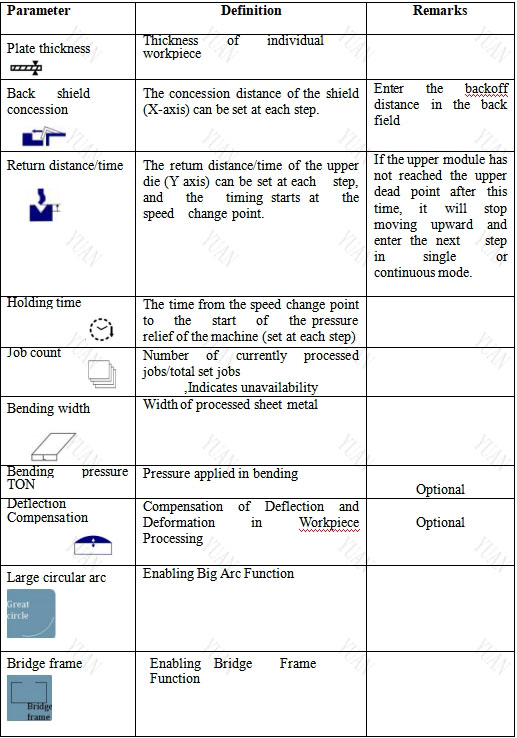
Click to ![]() display more data settings,Different working modes correspond to different pages. The following is the interface corresponding to the click mode:
display more data settings,Different working modes correspond to different pages. The following is the interface corresponding to the click mode:
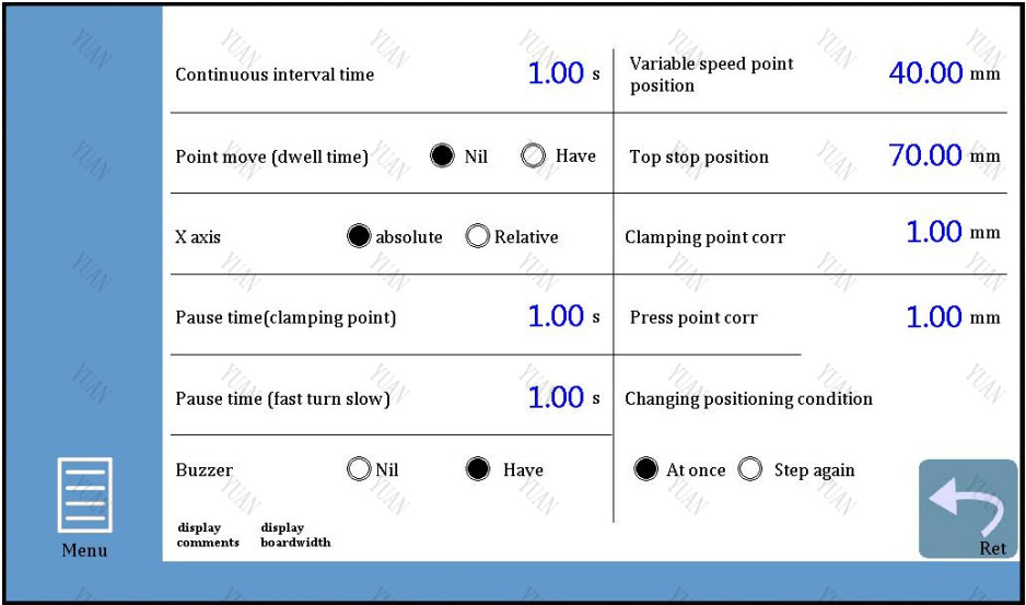
Table 1-2 Introduction of Parameters
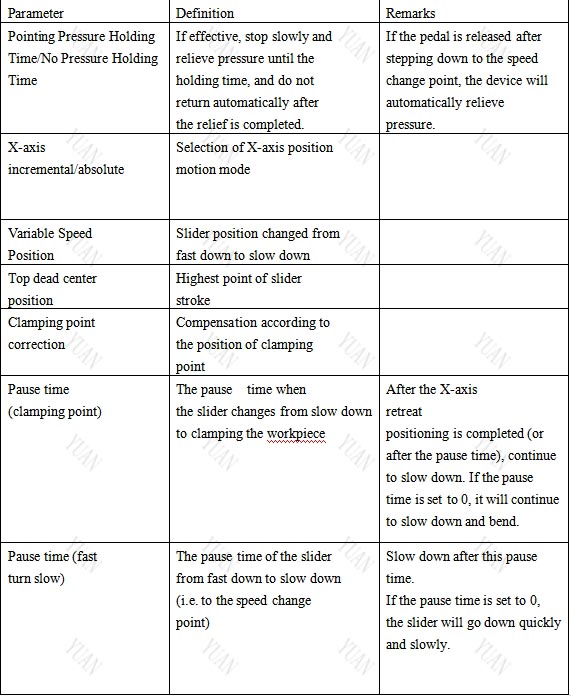
1.2 Parameter setting
Click on the menu icon on the main page of programming,Select "Parameter Settings" from the pop-up menu to enter the parameter settings page.
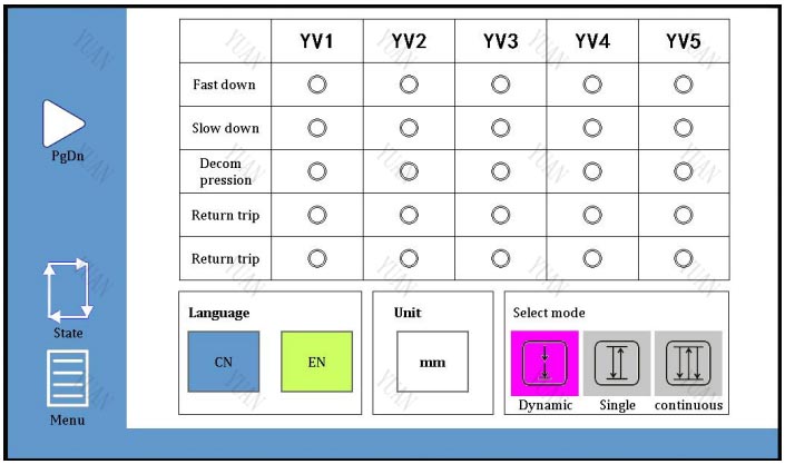
Operational parameters can be configured on this page. Please refer to the following steps for parameter setting.
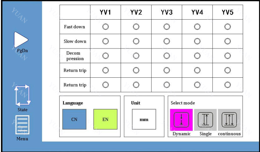
1. On the main page of parameter setting, you can choose YV1~YV5 valve output configuration, interface language and working mode. There are four motion states of slider: fast down, slow down, return trip and pressure relief. The output of four motion states may be different for different models, so the output configuration (YV1 ~ YV5) is needed here.
Interface Language Selection: Chinese and EN (English) Options.
Choice of working mode:Inch movement ![]() Single time
Single time ![]() continuity
continuity![]()
Table 1-3 Working Model
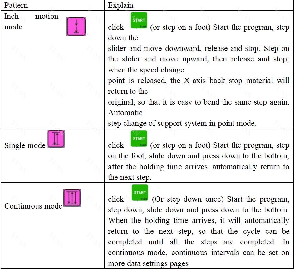
Please kindly take note:
1) Inch mode is used in calibration, single mode is used in normal operation, and continuous mode is used in testing machine.
2) In the "Manual Moving" and "X/Y/R Axis Navigation" teaching pictures, the mode automatically changes to the slow point mode, after exiting these pictures, it will
automatically switch to the original mode.
3) If you first step on the switch, then step on the switch is invalid; unlock the switch, then step on the switch.
If the program does not start, step on it for the first time(Or press on the screen![]() )It will start the program and step down again before moving downward.
)It will start the program and step down again before moving downward.
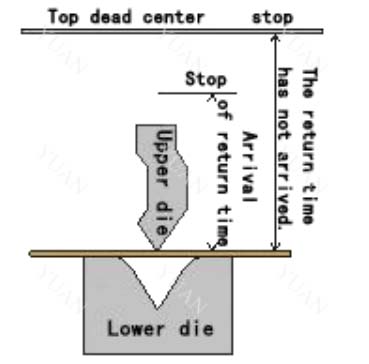
In single mode or continuous mode, the slider moves upward.If the return time is valid ![]() and the return time arrives (the slider has not reached the upper dead point), the slider will no longer move upward and enter the next step.
and the return time arrives (the slider has not reached the upper dead point), the slider will no longer move upward and enter the next step.
2.Click on![]() the page will pop up a dialog box prompting users to log in, please enter the correct password (0313), and then click
the page will pop up a dialog box prompting users to log in, please enter the correct password (0313), and then click ![]() again to start setting
again to start setting
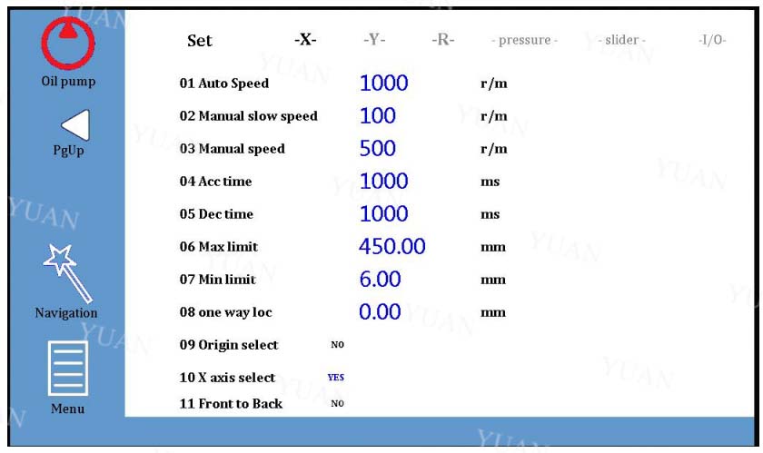
X/Y/R Axis Settings On the parameter setting page, the operator can set the motion parameters of the X/Y axis
(Y2/R axis is optional), as well as the pressure and slider parameters in the bending 11 process. Click "R Axis is valid" to enable the R Axis, as shown in the following figure:
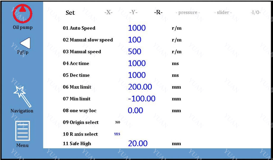
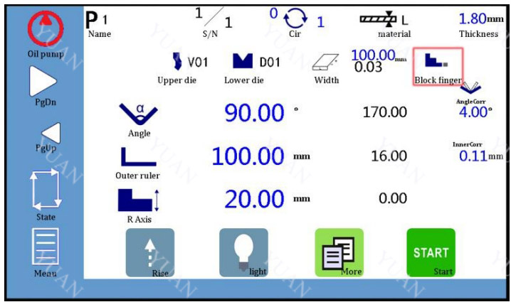
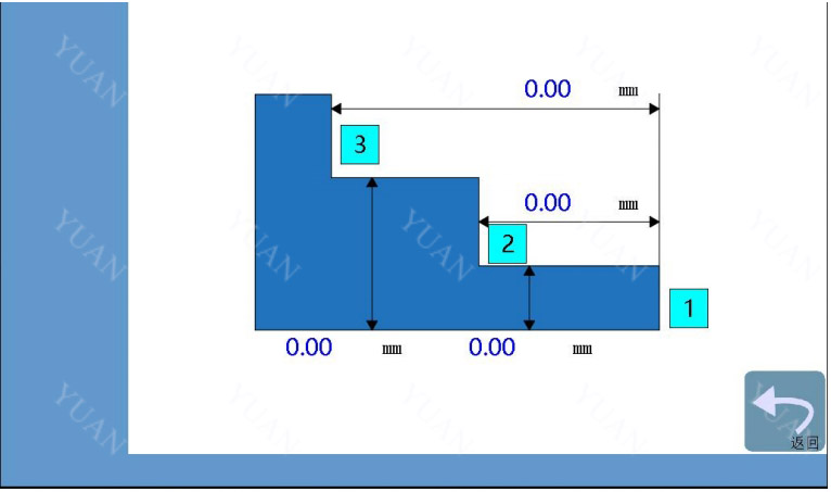
After that, the R-axis related information and setting icons are displayed on the programming page. Clicking on the red box ![]() , the gear parameters of the gear
, the gear parameters of the gear
finger can be set. It is convenient to select different gear according to the workpiece processed.
Pressure setting
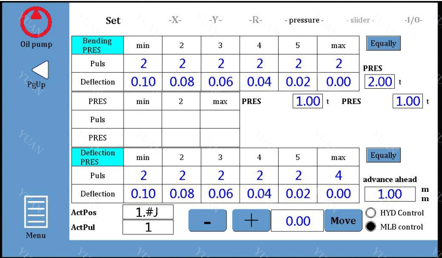
Operators can record the bending pressure and deflection under different electrical signals on the'-pressure-'page. The system will calculate the linear relationship between the
bending pressure and voltage, deflection and voltage according to the internal algorithm, so that the actual operation can be easily compensated according to the specific input
pressure and deflection values. Given that the simulated values of pressure and deflection are set on the Machine State page, see Chapter 1.3 Machine State for details.
Slider setting
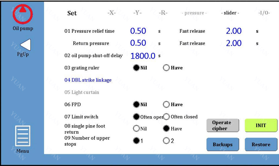
Operators can set relevant parameters on the'-slider-'page and set the grating ruler according to the actual situation, as shown in the following figure:
Please take notice.
1) Pressure relief time: The return journey begins after the duration of pressure
relief arrives. 2) Oil pump automatic shutdown delay: When the machine is not operated, the oil
pump automatically shuts down after the time arrives. Default: 1800 seconds, setting range: 300-3276.7 seconds.
Machine state
Operators can access machine status pages in a variety of ways. As shown below, on the main programming page, click on the icon![]() to enter the machine status page.
to enter the machine status page.
As shown below, you can enter the machine status page by manually moving the page and clicking on the icon on the left.
Click to "state"enter the machine status page
On the machine status page, the operator can observe the input/output signals of the system and analyze the possible problems more conveniently.
In the output window, click"forced" , and the lower window will display the functional control status of each output port, as shown in the following figure:
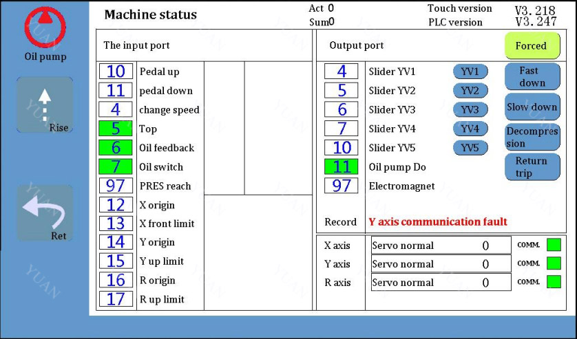
If the box corresponding to the input/output command shows green, it indicates that the signal or function is normal.
Pole: Set the maximum height of the rise, which can be set only after the grating ruler is selected.
Manual movement
Operators can move Y axis (slider), X axis (back shield) or R axis (finger shield) in manual mode.
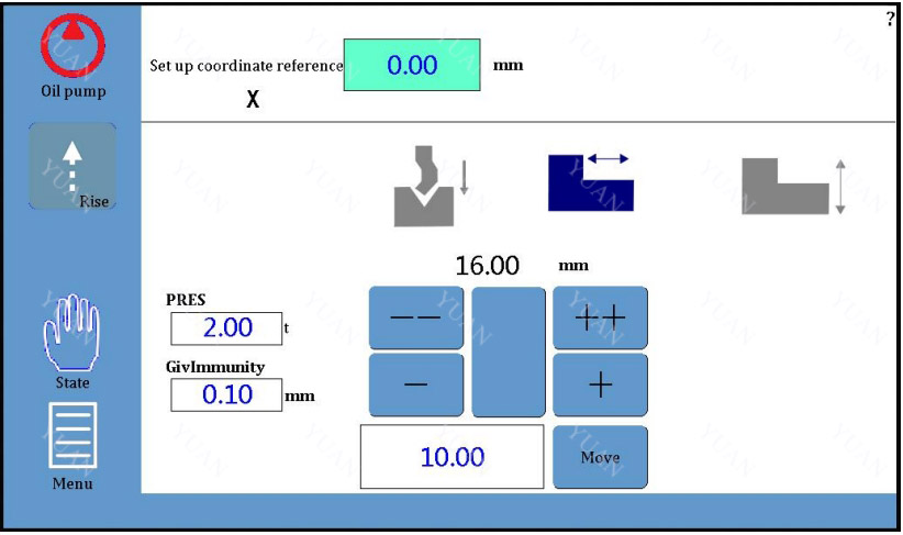
1. Click on the menu icon "menu"in the main page of programming, click on "Manual .Move" in the pop-up menu, and enter the manual page (to set the coordinates of X/Y/R
axis reference point, you need to enter the password "0313"):
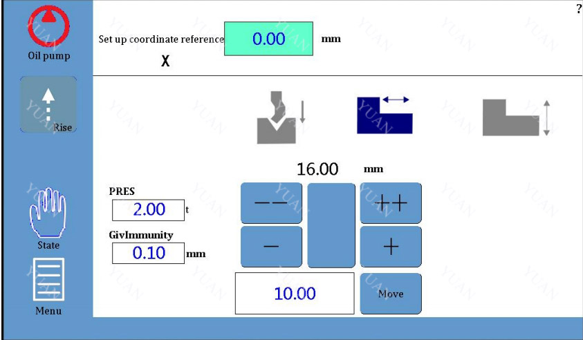
2. Setting up X-axis reference points Use the measuring tool to measure the length of a reference position (from clamping point
to back shield), and then write the measured value in the settings above the back shield
icon .
3. Setting up the reference point of Y-axis Step on the foot and press it down to the bottom. Then use the measuring tool to measure
the length of a reference position (from the bottom of the lower die to the top of the upper die). Finally, write the measured value in the settings above the slider icon .
4. Setting Reference Points for R-axis
The R-axis is used to select the finger shield, and the X-axis and R-axis can cooperate with the movement to prevent the collision of the die. Operators use measuring tools to measure the distance between the working plane of the lower die and the lower plane of
the stop finger, and write the measured values in the above settings .
5. In the above screen - /++ for manual slow/fast movement, click the "move" button on the
corresponding page, the X/Y/R axis will move the specified distance at the set speed, and
then click the button again to stop the movement. uSet the page at the reference point of the selected axis and hold it down . The motor of
the axis moves slowly in the direction of increasing count. uSet the page at the reference point of the selected axis and hold it down . The motor of
the axis moves slowly in the direction of subtraction. uSet the page at the reference point of the selected axis, press and hold , and the motor of
the axis moves rapidly in the direction of increasing count. uSet the page at the reference point of the selected axis, press and hold , and the motor of
the axis moves rapidly in the direction of subtraction. While moving the axis, the current value of the coordinates of the X/Y/R axis changes accordingly until it moves to the appropriate position. Attention: This system has the function of setting position limit. If the given position
exceeds the set minimum/maximum limit, the system will prompt "the given position
exceeds the limit" and invalid whenever it is pressed
1.5 Mould management
The numerical control system automatically calculates the programming value of X/Y/R
axis according to the selected die, bending angle and bending length. Die parameters are the basis of system calculation and must be accurate 1.5.1 Upper die editing
1.Click on the module icon on the programming page and enter the die editing page
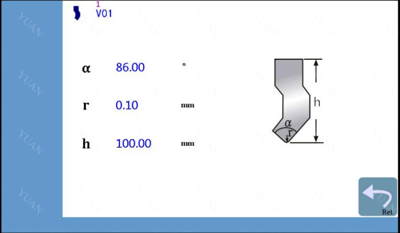
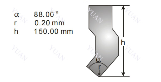
2.As an example, the upper model in the following figure is input (alpha: angle of upper model, r: chamfer, h: height of upper model)
3. After the data input is completed, click on the input field next to it and name the die
according to its own naming rules. The current model can be saved with the given naming. (Up to 30 upper model information can be saved)
4. After completing the above steps, the upper model data will be automatically saved for subsequent use. 5.Click on the top Icon ,Then click or you can browse saved die information. 6.Click on the top Icon ,Return to the programming page.
1.5.2 Lower mode editing
1.Click on the icon on the edit page ,Enter the die editing page as follows:
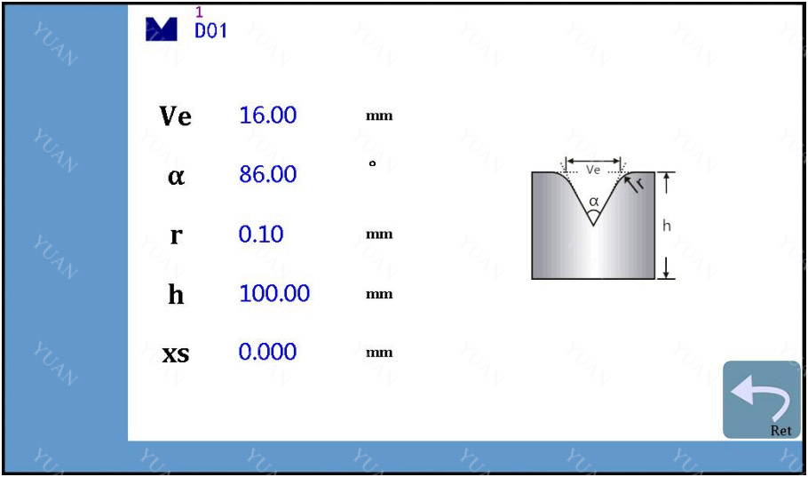
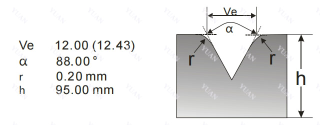
2.For example, input the lower mode data (Ve: width of opening, alpha: angle of opening, r: chamfer, h: height of lower mode)
3.After the input of the lower model data is completed, Click next input field,Name
the die according to its own naming rules, and save the current lower die with a name (up to 40 lower die information can be saved)
4. After completing the above steps, the lower model data will be automatically saved for subsequent use.
5.Click on the icon below ,Then click or you can browse saved moulds.
6.Click Icon ,return to the programming page.
2.Examples of application
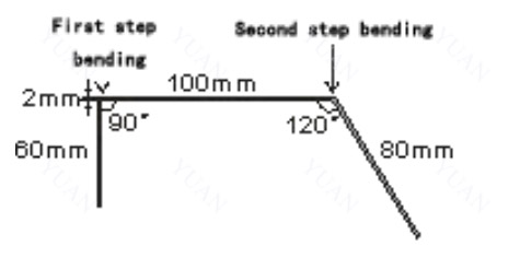
Combining panel and machine tool operation, this chapter introduces how to process a workpiece which needs multiple bending with a specific example. The X/Y axis position
and motion direction sketches are as follows:
This example is illustrated by programming the following products.
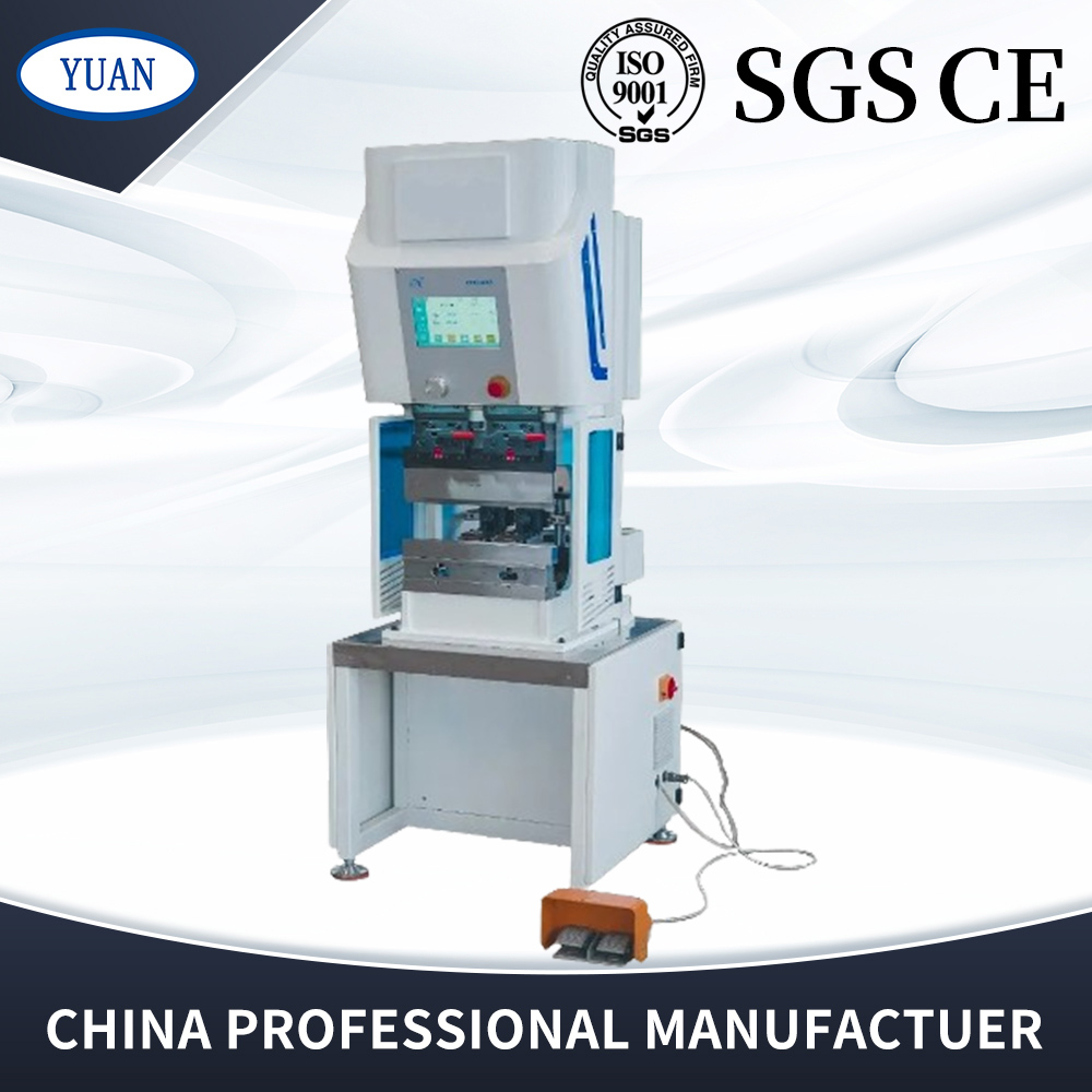 | 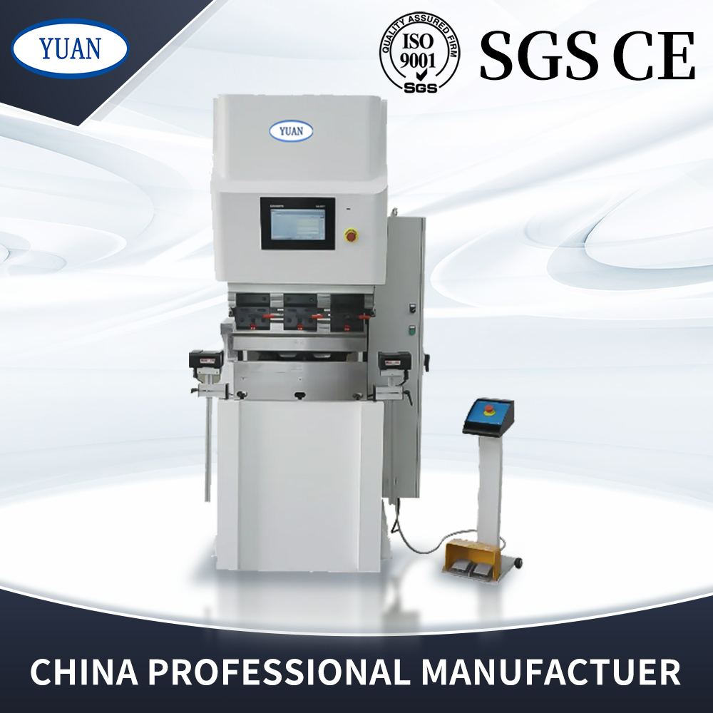 | 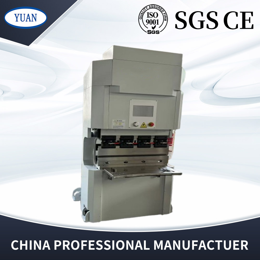 |
| Mini Press Brake | Small Press Brake | Electric Press Brake 18 Ton |