Brief Introduction of the content
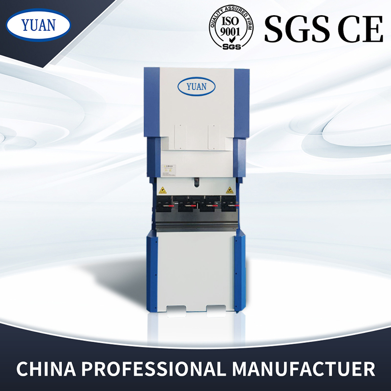
This manual mainly introduces the installation, technical specifications and application examples of ET16 hybrid press brake 40 ton 800mm control system products. The content of each section is summarized as follows:;
Chapter 1 (operation panel) introduces the use of the operation panel of thehybrid press brake 40ton 800 mm control system;
Chapter 2 (Application examples) illustrates how to operate the control system with examples;
The appendix provides common handling on each equipment of the system for users to browse quickly;
Suitable object
This manual provides the introduction of ET16 hybrid press brake 40 ton 800mm control system, to facilitate users and commissioning personnel to master the use of ET16 machine as soon as possible.
1. 1 Basic page introduction
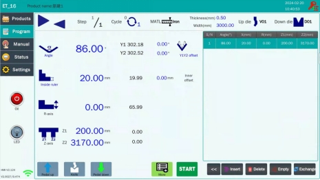
1.1.1 Programming page
The following picture is the programming homepage of hybrid press brake control system
1.1.2 Drawing page
Click the ![]() icon on the product library page to jump out of the new product box, select the graphics in the programming mode, and click
icon on the product library page to jump out of the new product box, select the graphics in the programming mode, and click ![]() to enter the drawing interface:
to enter the drawing interface:
Click the screen, you can draw the shape of the bent parts according to the drawing. The Angle and length of the bending can be changed in the parameter table of each step on the right side, according to the actual work.The piece processing requirements change the bending step sequence.
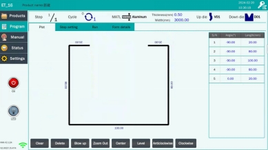
After editing, click the OK button to enter the step sequence adjustment page. After the step sequence is confirmed, you can start bending by running.
1.1.3 More data settings
Click the icon  on the main programming page to enter the more Data Settings page:
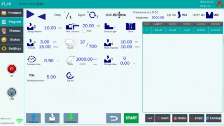
Note: After the knife is opened, the pedal will slow down
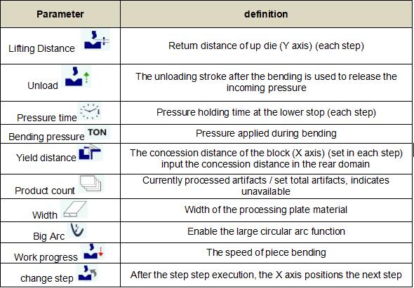
Table 1-1 A parameter introduction
Working mode selection: Inching![]() , Once
, Once![]() , continuous
, continuous ![]()
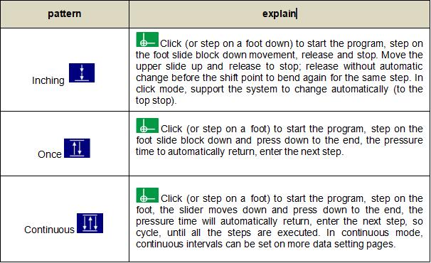
<remarks>
1) Spot moving mode is used on time, single mode is used during normal operation, and continuous mode is used when testing the machine.
2) In the "manual move" screen, the mode automatically changes to the slow click mode, and it will automatically switch to the original mode after quitting these screens.
3) If the pedal switch first, the pedal switch is invalid; release the pedal switch and the pedal switch.
If the program does not start, the first step down (or press on the screen) starts the program, and the second step down moves down.
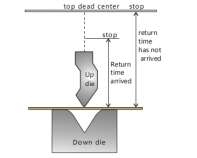
In single mode or continuous mode, the slider moves upward. If the return time is valid and the return time arrives (the slider has not reached the upper dead point), the slider no longer moves upward and enters the next step.
1. 2 Manual movement
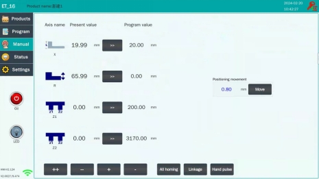
The operator can move the X-axis (rear gear), R axis (stop finger), Z axis in manual mode.
1. Click the icon on the main page to enter the manual page:
2. Set up the reference point of the X-axis
Use the measurement tool to measure the length of a reference position (from the pinch to the rear stop) and write the measurement in the setting above the rear stop icon.
3. Set the reference point of R axis R axis is used to select the block finger, X and R axis with movement can prevent collision mold. The operator uses the measurement tool to measure the distance between the working plane of the lower mold and the lower plane of the block finger, and writes the measurement value in the upper setting.
4. -, + / - -, + + is manual slow / fast movement, click the![]() button on the page, X / Y / R / Z axis will press.
button on the page, X / Y / R / Z axis will press.
Set the speed to move the specified distance, and click the button again to stop the movement.
On the reference point setting page of the selected axis, hold![]() , and the motor of the axis moves slowly in the direction of the reduction;In the reference point setting page of the selected axis, hold
, and the motor of the axis moves slowly in the direction of the reduction;In the reference point setting page of the selected axis, hold , and the motor of the axis moves quickly in the direction of the increase;
In the reference point setting page of the selected axis, hold , and the motor of the axis moves quickly in the direction of the reduction;
While moving the axis, the current value of the X / Y / R / Z axis coordinates changes until it is moved to the appropriate position.
<Note>: This system has the given position limit function, if the given position exceeds the set minimum / maximum limit, every time you press When the system will prompt "given position overrun" and
 invalid.
5. Click the icon to select X1X2, R1R2 and Z1Z2 to move both axes at the same time.
6. Click the icon, can achieve all axes back to the original at the same time.
1. 3 Machine status
1)Base page: On the home page, click the icon to enter the machine status interface:
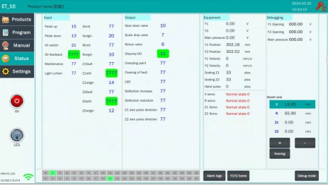
On the machine status page, the operator can observe the system input / output signals to more easily analyze the possible problems.
2)Debug mode: In the debug window, click  , and the function control status of each output port will be displayed in the lower window, as shown below:
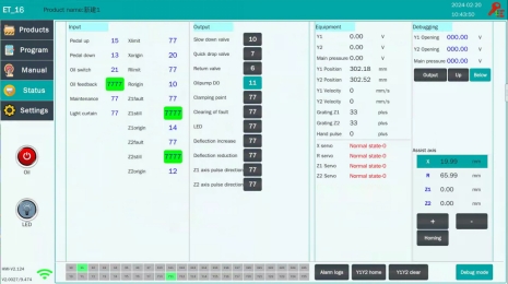
Manually calibrate the proportional valve pressure and manually move the slider up and down
Click the Force button to manually force the operation
Fast down: Give Y1,Y2 negative voltage, open fast down valve (recommended 1-2v)
Slow down: Give Y1,Y2 negative voltage, open the slow down valve (1-2v recommended)
Return: Give Y1,Y2 negative voltage (recommended 1-2v), give main pressure (recommended 1-2v)
Y1Y2 Clear: Clear the current Y1Y2 position feedback
Y1Y2 home: can achieve Y1Y2 one-click back to the original
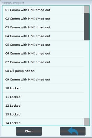
Click the alarm log icon at the bottom of the machine status interface, and the historical alarm record table will pop up, as shown below:
1. 4 System Settings
1.4.1 User
Click the icon on the main page to enter the user parameter interface:
1) Basic parameters
Language : Chinese, English, Russian,Italian,Spain ,Abrabic French
Unit: millimeter, inch
Set display: Y1Y2 displays the target location
Theme select: Different color themes can be selected
2) Program parameters
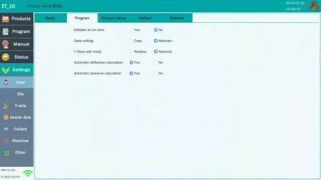
Editable at run time: Other parameters can be edited during product processing
Deep editing: copy the option, modify the Y1 value Y2 to follow the change; keep the option, modify the Y1 value Y2 does not follow the change
w Y deep edit mode: relative option, the corresponding depth is negative; absolute option, the corresponding depth is positive
w Automatic calculation of parameters (bending pressure and deflection): After the bending pressure and deflection change with relevant parameters
3) Product setup
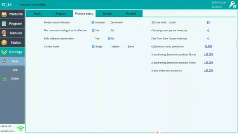
The pressure holding time is effective: to the pressure retention time, stop the slow down and pressure relief, and will not automatically return after the pressure relief is completed
If the foot step down to the speed point after releasing the foot, the device will also automatically release pressure
Safe distance deceleration: after opening, the X-axis safety distance will slow down
Pause time: after the pause time) and then continue to slow down, if the pause time is set to 0, it will always slow down and bend.
Fast turn slow pause time: the pause time of the slider from fast to slow (i. e. reaching the shift point). After this stop.Slow down after the time. If the pause time is set to 0, the slider will slow down quickly.
Calibration clamp point: compensate according to the position of the clamp point, and the X-axis performs the concession. The value is positive, and the X-axis edes in advance.
X positioning ,transition position R:To prevent the R axis from hitting it to a certain height when the X axis is positioned.
Z positioning ,transition position X:In order to prevent hitting the X axis, give a certain distance on the Z axis.
Z-axis offset distance:The Z axis is the safe offset distance set to prevent collision.
1.4.2 Die
The CNC system automatically calculates the programming value of X / Y / R axis according to the selected mold, bending angle and bending length.
The mold parameters are the basis of the system calculation, and they must be made accurate.
Click the  icon on the main page to enter the user parameter interface:
1) Up die
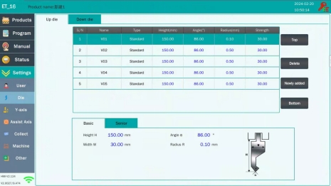
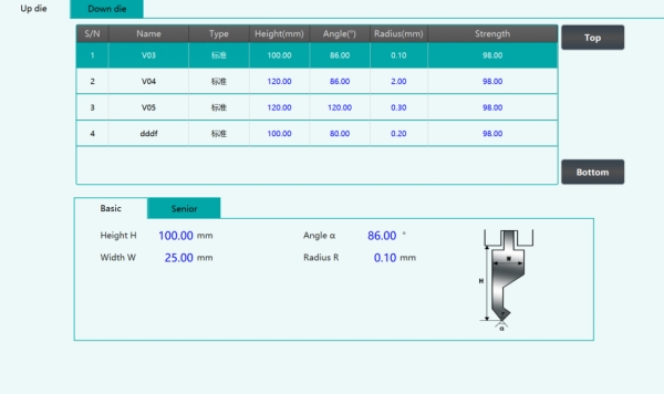
1. Input the upper die data (α: Angle, RA: radius, H: height, W: width)
2. The mold parameter table can also directly name and modify the mold according to its own naming requirements
3. After the above steps are completed, the mode data will be automatically saved for subsequent use.
4. When the number of molds is stored more, click  or
or you can quickly browse the saved mold.
2) Down die

2. Input the upper mode data (α: Angle, RA: radius , H: height, W: width, V: opening length, X safe distance)
3. In the mold parameter table, you can also directly name and modify the mold parameters according to your own requirements
4. After completing the above steps, the lower template data will be automatically saved for subsequent use.
5. When the number of molds is stored more, click or
or  you can quickly browse the saved mold.
1.4.3 Y-axis setting
Note: On the main programming page, clicking the icon will pop up the numeric keyboard. Please enter (9527) to enter other hidden parameters interface.
Click the  icon on the main page to enter the Y-axis parameter interface:
1) Basic parameters
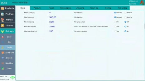
2) Pressure
The operator can record the bending pressure and deflection under different electrical signals under the Pressure page.

Machine tonnage: input the actual tonnage of the machine
w Valvalue: input to voltage, just output pressure (recommendation 5)
w Bending stress factor: the coefficient of bending pressure calculation, the initial value is 0.1, the calculation pressure is small, and appropriately increased
For pressure measurement, for example, after measuring 5Mpa, if the given voltage is cleared, measure the voltage corresponding value to other Mpa voltage again. If the zero clearance operation is not performed, the measured voltage will have a deviation, and repeat the corresponding voltage to observe the corresponding pressure value
3)Faster
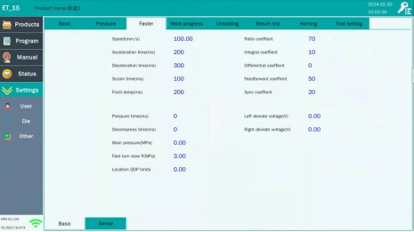
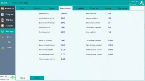
4) Work progress
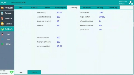
5) Unloading
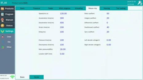
6) Return trip
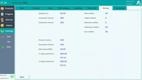
7) Homing
8) Tool setting
Click the ![]() icon on the main page to enter the auxiliary axis parameter interface:
icon on the main page to enter the auxiliary axis parameter interface: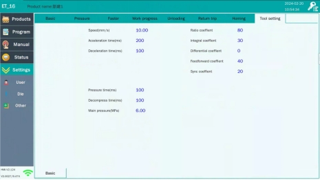
Click the  icon on the main page to enter the auxiliary axis parameter interface:
1) Basic parameters
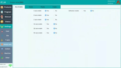
X-axis enable: whether the rear gear can move back and forth
w R-axis enable: whether the rear gear can be moved up and down
w Z-axis enable: whether the rear gear can be moved left and right
w Deflection enable: whether there is a deflection compensation
w Servo pump enable: whether the oil pump motor is a servo pump
2) X-axis
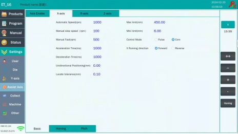
3) R-axis
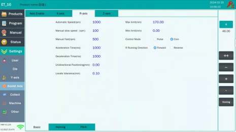
4) Z-axis
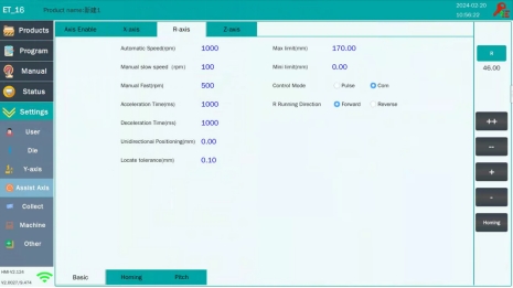
1.4.5 Datacollection
Click the  icon on the main page to enter the data collection interface:
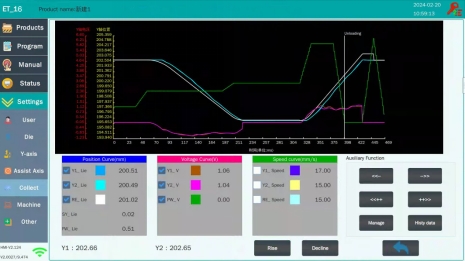
Click the icon to view the collection of historical data, click the
 icon to transfer data storage with USB, delete.
1.4.6 Machine
Click the icon on  to enter the machine page:
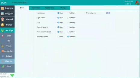
Hand pulse: hand pulse, deep bending mode, do the stop point correction
Light curtain: optional, light curtain protection
LED: equipment lighting function
Front stop: (QX + Z1Z2)
1.4.7 Otner
1) System management
Click the  icon on the main page to enter the system management page:

wBackup: you can transfer and delete between local files and USB. Backup here is the parameters [upper mode, lower mode, material, input and output, axis parameters, slider parameters, parameters advanced parameters in the function is on]
Upgrade: can be update and upgrade
Operation password: can change the operation password, enter the required level password, the advanced password can change the low-level password
Replace image: Replace the picture after inserting USB, and take effect after power failure and restart
Factory reset: all data restore factory settings (no unauthorized change, resulting in data loss)
Click the icon on  to enter the operation log page:
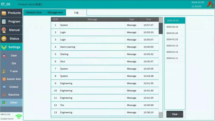
This page allows you to view historical operation records.
![]()
![]()
![]()
![]() 2 Application examples
2 Application examples
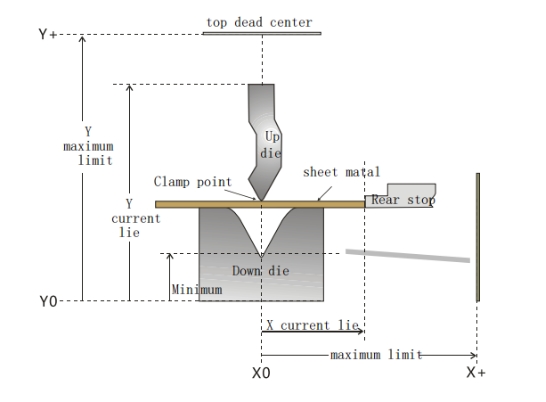
This chapter combines panel and machine tool operation to provide a specific example of how to process a workpiece that requires multiple bends. The X / Y axis position and movement direction are shown as follows:
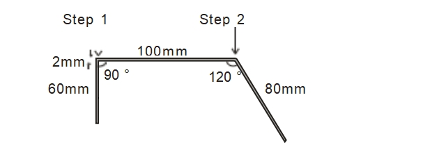
This example is illustrated by programming the following product:
1) If there is an emergency or the need to return during the operation, you can click  the button to return to the top dead point.2) If the rear barrier
concession distance is set, the rear baffle starts to yield after the clamp time arrives.
1. Select the lower mold opening Ve
Referring to the following table, the thickness of the bending plate is 2mm, so it is necessary to choose the groove of 6 times the width of the plate thickness, that is, the bending groove Ve should choose 12mm. Criteria for selecting lower mold opening
Workpiece thickness T (mm) | 0.6~2.5 | 3~8 | 10~50 |
Width W (mm) | 6T | 8T | 10T |
2. Bend step order
Step step 1: the bend angle is 90.00 ° and the bend length L is 60.00mm
Step sequence 2: the bending angle is 120.00 °, and the bending length L is 80.00mm
3. Selection of working mode
Three working modes are available: dot move, single, continuous.
These working modes support automatic change, after the first step will automatically go to the next step.
<Note> Refer to section "1.1.3 More Data Settings" for details of the working mode.
2.2 Operation steps
First, turn on the main power switch on the power cabinet, and then start the oil pump (the machine does not operate at this time).
<Note> Do not press the emergency stop button, otherwise the machine cannot act and the oil pump cannot start.
2. Display the panel base settings
1) Click the icon on the programming main page and enter the plate thickness (2mm).
2) Click the  icon (top / down mold) for editing in the page.
The up die is edited as follows:
3) Click the  icon on the main programming page to enter more bending data:
<Note> Please refer to section "1.1.3 More Data Settings page" for details.
3. Calibrate by manual movement mode
The operator can move the Y axis (slider), X axis (rear gear) and R axis (stop finger) Z axis in manual mode.
1) Click the  icon on the main page to enter the manual page.
2) Click- - / + + or button to move the selected Y (slider) / X (rear gear) / R (finger) Z axis. While moving each axis, the current value of the axis coordinate changes until it moves to the appropriate position.
3) Set up the reference point of the X-axis
Use the measurement tool to measure the length of a reference position (from the pinch to the rear gear) and write the measurement in the rear gear settings.
A method of measuring the length of the rear block from the clamp point: after moving the X axis, take a piece of board between the top and the lower mold, and push the board to make the one side of the rear gear; then step on the foot, make the upper mold move down to just press the board (a little strength but the plate material is not deformed), and finally step on the foot to make the upper die back to the dead point, and measure the vertical distance between the imprint trace and the small plate on the rear gear side, that is, the length of the clamp point to the rear gear.
Appendix:Table B-1 Analysis and handling of common problems
problem description | Reasons and solutions |
The oil pump cannot be started | . Whether the emergency stop button is released. . Whether the oil pump feedback signal is normal. . The oil pump icon on the touch screen is pressed for 3 seconds. |
The oil pump is stopped after starting | . The self-off delay of the oil pump is set too short . The contactor coil is loose . The oil pump feedback signal is loose and the emergency stop |
Servo communication is not available | Whether the communication line between CPU and rear gear servo, servo and servo is well connected. |
The XR axis servo (manual) cannot move | . Servo communication is normal Whether the servo alarm (if the alarm cannot be cleared, it needs to be reagain). Whether the motor wire is connected or not. |
After the parameters are set, press the "START" on the touch screen or step on the foot switch | . Whether the emergency stop button is released. Whether the oil pump is open. . Whether the servo is normal. |
The slider has an abnormal movement | . Check whether the pressure retention time "pressure relief time" and "return time" are set reasonably. . Whether the variable speed point and the dead point information is normal. . Oil pump start . Emergency stop switch is released Enter the manual moving screen (if the XY axis is not adjusted at this time) |
The bending angle error of the first knife is very large (> 5 °) | Whether the knife mold is relatively flat. Measure Whether the height after the drop is consistent with the height calculated by the system, if not. . Check whether the set knife mode parameters and plate thickness are correct. . Whether the accuracy of the selected wire rod (belt) is not enough. Whether the thickness of the workpiece plate and the selected abrasive tools are reasonable, see point 1 in section "2.1, example description" of the selection rules . The work piece is made of very elastic steel, which requires Angle compensation. |
The X-axis automatic mode positioning is not in place | Whether the rods on both sides of the bending der are not parallel, causing the motor to move to a certain position; verify the X-axis during manual movement, if the problem exists. |
Wide version bending angle error | . Check that the machine pressure is adequate |
Calibrate the Angle, and bend the Angle after changing a material | The bending parameters of different materials and different widths should be set and compensated separately. |
Next step sequential bending angle error | . Whether the grinding number used in the next step changed. |
The angle compensation value is wrong | . Beyond the die safety height, the system automatically limits ([bending depth + compensation]> minimum height). |